To customize the user interface by work flow:
Click Tools, Customize, or right-click in the window border and select Customize.
On the Options tab, under Work flow customization, select one or more of:
Consumer product design
Machine design
Mold design
Click OK.
Special menu and toolbar settings are made for Consumer product design, Machine design,
or Mold design. After the software is initially installed, you only see this screen once, but you can
change all the options in other places, including the Options tab in the Customize dialog box.
The three-workflow customizations affect the interface as follows:
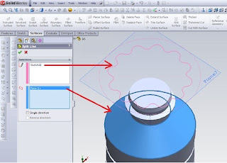
Consumer product design adds the Surfaces toolbar to the CommandManager.
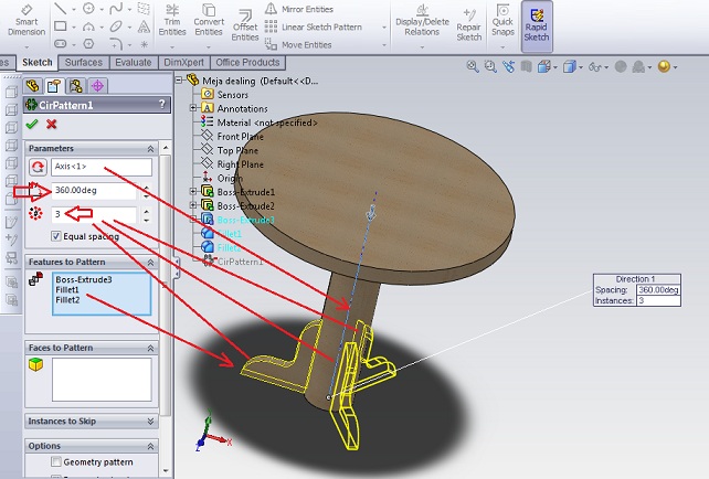
Machine design adds Sheet Metal and Weldments toolbars to the CommandManager.
Mold design adds Surfaces and Mold Tools toolbars to the CommandManager.
Similar changes are made to the menus to hide or show menu selections as appropriate. You can
find more information about hiding and showing menu items later in this chapter.
If you want to select a different option after the initial setup, choose Tools ➪ Customize and click
the Options tab, where you can specify a different choice. Figure 2.20 shows the Options tab of the
Customize dialog box.
Archive for 2012
Split Line tool
Split Line tools to project entities such as sketches, solid, surface, face, plane, or surface spline to surfaces, or curved or planar. It divides the selected face into several separate face. we can divide the curve on some solid body with a single command. We can make a line following divisions: Projection. Projection sketch on the surface. We can divide the pattern line features created using projection curves. We can make use of text split line sketch. This is useful for making items such as decals. Silhouette. Make the split line on the cylinder. Intersection. Splits face with intersecting solid, surface, face, plane, or spline surface. When we make a line break with an open profile sketch, sketch must span at least tw
o sides of the model
.
Creating Lines Split When we made the split lines, edges do not change that can be reused in the downstream and changed the update feature edges. In this model we insert line splits at the front face as the last item in the FeatureManager design tree. If we change the order Line1 Split follow Extrude1 features, models defend downstream chamfer and fillet.
To create a projection split line:Click Split Line (Curves toolbar) or Insert, Curve, Split Line. In the PropertyManager, under Type Split, select Projection. Under Selection, click: A sketch for Sketch for the Project. We can choose some of the contours of the same sketches to share. face-face to project sketches for face to Split. One way to project the split line in only one direction.Click OK. To create a split line silhouette:Click Split Line (Curves toolbar) or Insert, Curve, Split Line. In the PropertyManager, under Type Split, click Silhouette. In Selection: Select the plane to the project through the silhouette of the model (the outside) for Direction of Pull. Select the face to face project for the plane to Split. face can not be planar. Set Angle to create a draft angle.Click OK. To create a line of cleavage junction:Click Split Line (Curves toolbar) or Insert, Curve, Split Line. In the PropertyManager, under Type Split, select Intersection. In Selection: Choose a splitting tool (solid cut, surface, face, plane, or surface splines) for Non Separates / face / Planes.Click on the face / body to Split, and select the target face or body that projected splitting tool.Click OK
Comments Off
Solidworks Boss-Extrude, circular pattern
Step 1. Create a circle with a diameter of 85 sketches, on the top plane
Step 2. Boss-Extrude1, to create a pedestal table.
Click Insert> Boss> Extrude
From the property manager, Direction 1
select offset, input the number 75
select the Blind, with a thickness of 5
Step 3. Create a circle with a diameter of 15 sketches, the top plane.
Step 4. Boss-Extrude2, to make the pole
table.
Click Insert> Boss> Extrude
From the property manager, Direction 1
select the Up to Surface
select the face that will be made in
reference
Last step. circular pattern, to create a table leg.
Click Insert> patern / mirror> circular pattern
Comments Off
Autocad, Quick Properties
The latest from the Quick Properties is a tool that allows us to be able to see and change object properties in place,
without having to go to the Properties palette. we can also change the Quick Properties (QP) or off of the status bar.
After turning the feature on the position on, simply select an object and properties for editing.
You can control the display properties for each object in the CUI (for quick access select the Customize button QP).
The new Quick Properties tab in the Drafting Settings dialog box provides additional control.
Comments Off
Unigraphics, Part Navigator
Sketches can be created by selecting a Section Sketch icon in the creation of certain features such as Extrude and Revolve dialog, select the Sketch icon directly on Form Feature toolbar, or by selecting Insert> Sketch.
If we make a sketch of the feature creation dialog, section sketches remain internal to the feature. It does not display in the graphics window or in the Part Navigator. we can edit the sketch to access related features. If the sketch is needed to make additional
feature, you can select Make External Sketch of MB3 popup menu in the Navigator section and will appear in the graphics window.
If the sketch is not created from the feature creation dialog, it will appear as a separate feature in the Navigator section.
Comments Off
Making the Cut Extrude use offset
Set the initial conditions to extrude cut feature with offset
As we embark on the plane cut extrude the sketch plane offset from there.
We have to adjust the offset distance and enter into the Offset Value property manager ..
If necessary, click Reverse Direction to extend the features in the opposite direction from that shown in the preview.
Apply one or more features for multibody parts by selecting the Geometry pattern selection, and use the Scope feature to choose the body.
We have to create a model that we want to add a feature to multibody parts before adding the feature.
If we add a new body with a model that intersect with features, body-new body also regenerated to include the feature.
If we add a new body with a model that intersects the features, we need to use the edit feature to edit repel feature, choose a body-body, and add them to the list of the selected body. If we do not add a body to the list of the selected body, they remain intact.
When we first create models with multibody parts, automatic features intersecting process all the relevant sections. Auto-select is faster than all the body because the body only at the beginning of the list and does not regenerate the entire model. If we click on the body and clear Selected Auto-select, we must choose the bodies in the area of graphics that we want to include.
Comments Off
Autocad, Creates mirror an object.
This Menu mirror is very useful to create symmetrical objects because we can quickly draw half the object and then reflects the image the whole objects. we flip the object on the axis, called the mirror line to create a mirror image. To determine the line of the mirror while, we enter two points. we can choose whether to remove or retain the original objects.
Mirroring work in parallel to the plane XY of the current UCS.
To make a mirror object:
1. From the Modify menu, select Mirror.
2. Select the object to the mirror.
3. Specify the first point of mirror line.
4. Specify the second point.
5. Press ENTER to retain the original object, or enter y to delete the object in a mirror.
1. From the Modify menu, select Mirror.
2. Select the object to the mirror.
3. Specify the first point of mirror line.
4. Specify the second point.
5. Press ENTER to retain the original object, or enter y to delete the object in a mirror.
Comments Off
Solidworks, surface knit.
In the Solidworks facility helps us create a 3D solid, namely surface knit.
Knit Surface tool is used to combine two or more faces or surfaces into one.
Below the surface edge must be adjacent and non-overlapping (overlapping).
The position of the surface does not need to be in the same plane.
Try to choose an adjacent surface.
Click knit solid when the solid surface or solid form.
Select Merge to merge the entities face the same basic geometry.
Below the surface edge must be adjacent and non-overlapping (overlapping).
The position of the surface does not need to be in the same plane.
Try to choose an adjacent surface.
Click knit solid when the solid surface or solid form.
Select Merge to merge the entities face the same basic geometry.
Choose Gap Control to view or modify the tolerance gap knitting.
To make the surface follow langkah2 knit follows:
Click on the toolbar Surface Surface Knit, or click Insert, Surface, Knit.
In the PropertyManager,
Select the surfaces of adjacent surfaces, non-intersecting
Select faces or surfaces to be in Knit.
Select Try to form solid to create a solid model of a closed surface.
Select Merge to merge the entities face the same basic geometry.
Select the face to knit
Select Control Gap to see some edge gaps as possible, and to view or edit the tolerance limits or gaps.
See Knitting tolerance, make modifications if necessary.
Click OK.
Comments Off
Unigraphics, create a simple extrusion using a sketch
We will start using the existing facilities in Unigraphics to draw 3dimensi. One of the facilities we will use to draw 3d is Extrude
Use this facility to create a body with sweeping 2D or 3D profile curve, edge, face, sketch or feature curve is linear distance in a certain direction.
The steps create a simple extrusion using a sketch
1. Select the Extrude option, a dialog bar that displays the Extrude dialog.
2. Setting Selection of Intent to Add Connected.
3. To select a set of strings profile curve or edge, or a sketch.
Preview display features extruded using a default value.
4. Limit Pull the handle, or use the distance field in the dialog box or in a dynamic input to the desired size of the extrusion.
5. Click OK. Recommended extrusion has been made
Comments Off
Autocad, Rotating Object
If we design changes or we pull the wrong angle, we may need to rotate one or more objects that we make.
we can easily rotate an object or objects around the basic point that we specify.
Base point is usually the object snap points on the object.
To demonstrate the rotation, determine the angle of rotation.
By default, the zero is to the right, and increased degrees if counter-clockwise.
To change the default, select Format> Units
By setting a negative angle, we can change the object clockwise.
To rotate the object, choose Rotate from the Modify toolbar and select one object.
Alternatively, select the object and then select Rotate from the Modify toolbar.
Specify base point: prompt, indicating a point about what we want to play.
Specify rotation angle or [Copy / Reference]: prompt, type the angle on the command line.
Use the Copy option to make a copy of the original object.
Once we use the copy option, the prompt return of the same so that we can determine the angle of rotation.
Eventually there will be two objects, one in the original rotation angle and rotation angle new one.
Comments Off
The new features rib
The Rib PropertyManager appears when we make new features rib, or when we are editing an existing feature rib.
PropertyManager controls the following properties:
Parameter
Thickness. Adding thickness to the selected side of the sketch. Select one of the following:
First Side. Adding material to only one side of the sketch.
Both Sides. Adding the same material to both sides of the sketch.
Second Side. Adding material just to the other side of the sketch.
Rib Thickness. If we add the draft, we can adjust the thickness of the sketch plane or at the interface of the wall.
In the sketch plane
At the wall interface
Extrusion Direction. Select one of the following:
Parallel to Sketch. Creating rib extrusion parallel to the sketch.
Normal to Sketch. Creating normal rib extrusion sketch.
Flip material side. Changing the direction of extrusion.
Draft On / Off. Adding draft rib bone. Set the Draft Angle to determine the degree to draft.
Draft Outward (Available when the Draft On / Off selectable). Creating a design corner outside. If cleared, creating a design into the corner.
Comments Off
Unigraphics, make a line with an offset
If we choose the offset, we select a line that was created as a baseline (reference site) to make a line offset.
This is useful if we want to more quickly make a lot of lines where each line offset is made from the previous line.
Steps - steps that must be done to make a line with an offset:
1.Select menu offset curve
2.Select the object that will be offset
3.klik OK on the tool offset curve
4.tentukan distance you want to create
5.klik OK to terminate the process
Comments Off
To create a dimension angle (Angular Dimensions)
We can also determine the dimensions of angle by determining the angle point and end point.
When we make a dimension, we can modify the contents of text and harmony before deciding on the location of the line dimensions.
We can make the dimensions of the baseline and angle relative to the dimensions of the existing angle.
Corner of Baseline and dimensions are limited to 180 degrees or less. To obtain baseline and follow-dimensional angle greater than 180 degrees,
use grip editing to stretch the location of line extensions of existing basic or advanced dimensions.
Dimension Lines
If we use two straight, nonparallel lines to determine angle, dimension line arc spans the angle between two lines.
If the dimension arc line does not meet one or both of the dimension line, AutoCAD draws one or two line extensions to cut the dimension arc line. arc is always less than 180 degrees.
Dimension Circles and Arcs
If we use the arc or a circle or three points to determine the angle, arc-dimensional AutoCAD draw the line between line extensions.
Extension line drawn from the point of intersection of the line endpoint to arc dimensions.
We specify a location to determine the dimension arc line quadrant of the angle dimension.
To create a dimension angle (Angular Dimensions)
From the Dimension menu, select the angle.
Use one of the following methods:
For the dimension of the circle, select the circle at the end point from the point first and then determine the end point of the second corner.
For dimensions of other objects, select the first row, then select the second row.
Enter the options as needed:
To edit the text content of the dimensions, enter t (text) or m (multiline text). Editing or overwrite in brackets (<>) change or eliminate the value dimension is calculated by AutoCAD. Adding text before or after the parentheses add text before or after the value dimensions.
To edit a point of dimension text, insert (Angle).
Determine the location dimension arc line
Comments Off
Solidworks, Extruded Cut
This model can be a single part or parts of multibody.
To cut a solid drawing model with this tool, should we specify the basic model view which one to cut.
The next step make a sketch, based on the features to be used as a cutting tool.
Features that we choose depends on Our basic model and the form that we want to cut.
To cut a solid drawing model with this tool, should we specify the basic model view which one to cut.
The next step make a sketch, based on the features to be used as a cutting tool.
Features that we choose depends on Our basic model and the form that we want to cut.
Use this feature to cut down on the
drawing
model.
Extruded Cut
Cut-revolved
Cut-swept
Cut-lofted
Cut-Thickened
Extruded Cut
Cut-revolved
Cut-swept
Cut-lofted
Cut-Thickened
Cut with Surface
Comments Off
Unigraphics of CAD
We can design a autocad drawing 3D with assistance to facilitate and speed up our design.
This import command allows us to choose the type of geometric constraints that apply automatically to our sketch.
NX geometry analysis in an active sketch will implement the chosen constraints.
This function can be very useful when we add to the sketch geometry active,
NX geometry analysis in an active sketch will implement the chosen constraints.
This function can be very useful when we add to the sketch geometry active,
especially if the geometry is imported from the system in the form of CAD (DWG)
Comments Off
AutoCAD Hatch
This pattern is used to distinguish the components or to indicate the
materials that make up an object.
We can use predefined hatch pattern, determine the pattern of simple lines
using the current linetype,
or create a hatch pattern is more complex.
We can also create a gradient fill, which use transitions between shades of
one color or between two colors.
We can drag and drop hatches from the tool palette or use a dialog box with
additional options.
We can choose among several methods for determining the boundaries of hatch,
and we can control whether the hatch automatically adjust when boundary changes are made.
To reduce the file size, hatch patterns defined in the database image as a single graphic object.
In AutoCAD, we can use several methods to add hatch
patterns to our image.
Use a palette toolst when we need the speed and convenience.
With the Tool Palette window open, you can click right to access the Tool Properties dialog box from the shortcut menu.
This dialog box contains several options hatch patterns are also available through BHATCH.
Here we can determine the scale and spacing for hatch pattern.
In AutoCAD there are more than 50 industry-standard hatch patterns that we can use to distinguish the component object.
AutoCAD has a hatch pattern 14 which in accordance with ISO (International Standards Organization) standard.
biila we choose the ISO pattern, we can determine the width of a pen, which determines lineweight in the pattern.
When we make a hatch, by default hatch boundary drawn on the back hatch.
This makes it easier to see and select a hatch boundary.
We also can set your own hatch pattern using a linetype by filling out the dialog box,
or we can create more complex hatch patterns.
To create a hatch (shaded) in autocad
initial step that must be done is on the Draw menu, click Hatch.
In the Boundary Hatch and Fill dialog box, click Pick Points.
Determine the point in every area of the image that we want to create a hatch, and then press ENTER.
In the Boundary Hatch, Fill dialog box, Hatch tab, and swatch box, make sure that the sample pattern is the pattern we want to use.
To change the pattern, select another pattern from the Pattern list.
To see how the hatch pattern that we created, click the [...] button next to the Pattern.
Click OK when finished to see the preview.
-------------------------------------------------------------------------------
SOLIDWORK, UNIGRAPHICS, AUTOCAD, ILLUSTRATOR, PHOTOSHOP
Comments Off
SOLIDWORKS : Easy way to learn 3d solidwork
Now We will create a rectangle boss who refers to the previous discussion.
The first step to open the file before, then
Create a sketch for rec boss.
Click Extruded Boss / Base on the Features toolbar.
Select the top face on the object.
Top Click on the Standard Views toolbar.
Click Rectangle on the Sketch toolbar.
Move the pointer over the layout.
Begin drawing a rectangle
Click to place the end of the rectangle.
Move the pointer to create a rectangle.
Remove the pointer and click on PropertyManager to complete the rectangle.
Click Smart Dimension on the toolbar / Relations toolbar.
Select the rectangle.
Move the pointer on the rectangle and click to place the dimension.
Modification of the contents of the box and then click the desired dimension in the graphics area.
Now we make a sketch has been completed, Extrude the sketch to make the boss rec.
Click on the toolbar Sketch Sketch.
Click Trimetric on the Standard Views toolbar for a better view.
In PropertyManager, under Direction 1, set Depth to 15.
Click OK
Comments Off
Powered by Blogger.