Archive for 2020

Learn to make Solid Object modeling using the Loft solidworks method

Solid Object Modeling using the Loft method.
Example: Making a solid cylinder with R = 50 mm and a length of 200 mm.
1. Click the New icon, part icon, to create a new part.
2. Click the front icon, and the 2D sketch icon, so that we can activate the sketch tool.
3. Click the circle icon, and then from the origin we create a circle with R = 50 mm
4. Click the 2D sketch icon so that the sketch tool is inactive.
5. Click the isometric icon so that we get the circle sketch image in the isometric projection.
6. On the menu bar line, Click Insert, Reference Geometry, Plane. So that the Plane dialog box will be active as follows:


8. From the Plane box above, we click the plane, so that the right side will activate the Feature Manager Design Tree (FMDT). In FMDT, we click front
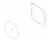
So that in the Selection section there will be Front text. After that, type 2000 mm and check the Reverse direction box.
9.Click the plane1 icon and the 2D sketch icon so that we can activate the sketch tool.
10.Click the circle icon, and then from the origin create a circle with R = 50 mm.
11. Then click 2D sketch so that the sketch tool is inactive. So that we get an image like the following:


12. Click the loft icon or on the menu bar click Insert, base, Loft. so that the Loft dialog box will be 
active as follows:


13. From the Loft dialog box above, click loft so that the right side will activate the Feature Manager Design Tree (FMDT). On FMDT click 3 and sketch 4, so that both sketches will be read in the group profile.
14. After the above process is complete, click the checklist so that we get a solid cylinder from the loft 
method.


Comments Off

Using Parametrics in Sketches Solidworks Tutorials

Sketching in SOLIDWORKS is the basis for creating features. Features are the basis for creating parts, which can be put together into assemblies. Sketch entities can also be added to drawings. What separates parametric CAD tools from simple 2D drawing programs is the intelligence that you can build in to a parametric sketch. In this tutorial, you learn some of the power that parametrics can provide in both structured using actual dimensions and unstructured changes. 1. Open a new SolidWorks document by clicking the New toolbar button or by choosing File, New. 2. From the list of templates, select a new part template, either inch or millimeter. 3. Press the Spacebar on the keyboard to open the View Orientation dialog box, and double click the Front view. 4. Right-click the Front plane in the FeatureManager, or whatever the first plane listed is, and select Sketch. 5. Click the View menu, and make sure the Sketch Relations item is depressed. This shows small icons on the screen to indicate when parametric relations are created between sketch entities. 6. Click the Circle from the Sketch toolbar, choose Tools, Sketch Entities, Circle. 7. Sketch a circle centered on the Origin. With the Circle tool activated, click the cursor at the Origin in the graphics area. The Origin is the asterisk at the intersection of the long vertical red arrow and the short horizontal red arrow. After clicking the first point, which represents the center of the circle, move the cursor away from the Origin, and click again, which will establish the radius of the circle.  8. Deactivate the circle by clicking its toolbar icon or pressing the Esc key on the keyboard. Now click and hold the cursor on the circle, then drag it to change the size of the circle. The center of the circle is locked to the Origin as the Coincident icon near the Origin appears. The radius is undefined, so it can be dragged by the cursor. If the centerpoint were not defined, the location of the center of the circle could also be dragged.

Comments Off

Customizing Toolbars Unigraphics Utility NX

The display of the toolbars as well as the display of each element within a toolbar may be customized. The display of a toolbar may be controlled in one of two ways: 
-Choose Tools→Customize from the main menu bar to access the Customize dialog. On the Toolbars page, choose the check box next to the toolbar name to display or hide it. The toolbars with a check are currently displayed. 
-Use the Third Mouse Button (MB3) within the NX window but outside the graphics window, to display a menu of all toolbars. The toolbars listed with a check box are displayed. Choosing a toolbar name with the First Mouse Button (MB1) will turn it on or off. The Customize option may be selected to access the Customize dialog 
-To turn on and off the display of icons within a toolbar, select the Toolbar Options area of the toolbar and choose Add or Remove Buttons, and the toolbar name. This will display a cascading menu with all of the available icons for the toolbar. Placing a check in the box next to the command will immediately display the icon in the appropriate toolbar. Removing the check will hide the icon.

Comments Off

Shortcut Keys Anchor Dockable Windows AutoCAD

The palette edge is the docking anchor. Once snapped together, you can drag all of them at once, provided you grab the palette at top left. The ability to anchor dockable windows is one of the best new features in AutoCAD. In case you haven’t noticed, there has been a proliferation of dockable windows in recent AutoCAD releases. These include the following: a Advanced Settings Dialog Command Line, Dashboard, dbConnect Manager, Design Center, External References, Info Palette, Lights In Model, Materials, Markup Set Manager, Properties, Quick Calculator, Sheet Set Manager, Sun Properties, Tool Palettes, Visual Style Manager. With all these dockable windows competing for space on screen, there is now officially no room left for drawing. Autodesk probably figured that it couldn’t just tell everyone to go out and buy three more monitors, so it invented the anchor feature. Right-click the vertical title bar of any palette (or, more correctly, dockable window), and toggle on Allow Docking, if it’s not already on. Repeat, and choose Anchor Left or Anchor Right. The best thing about anchoring is that you can anchor multiple dockable windows on each side of the screen without sacrificing any more pixels. Hover the mouse over any labeled anchored dock, and the associated palettes expand, filling all the available space. Anchoring is the most efficient way to work with dockable windows. Try anchoring as many palettes on the edges of the screen as your display resolution allows. You’ll have instant access to most of the UI without having to hunt for palettes in the menu or, worse yet, try to remember shortcut keys.

Comments Off

Sketching Dimensioning and Creating a Hole

Sketching a Hole
Create a circle for the center hole
Click Extruded Cut on the Features toolbar
Select the top face of the part
Click Top on the Standard Views toolbar
Click Circle on the Sketch toolbar
Move the pointer over the origin.The pointer changes to
Click to place the center of the circle
Move the pointer to create the circle.
Click to finish the circle and click OK in the PropertyManager

Dimensioning the Hole Sketch
Click Smart Dimension on the Sketch toolbar
Select the circle.3.Move the pointer and click to place the dimension
In the Modify box, type 25, then click OK and click in the graphics area

Creating a Hole
click exit sketch
click trimetric
in the propertymanager, under direction1, select through all for end condition
click OK.

Comments Off

Toolbars and commands Solidworks Desktop

· Posted in , , , , ,

When we open a new Part document you get additional toolbars and pull-down menus. Toolbars and commands are context sensitive. The commands that are available and related to what the user is doing are in color and the commands that are not available are shown gray. A new toolbar is the View Heads Up toolbar, at the top-center of the Graphics Area . It can be customized, as we shall see later. The question mark at the lower-right corner can be clicked to get help. SolidWorks Desktop for a New Part Document 1.SolidWorks logo 2.Main Drop-down Menu 3.Quick Access Toolbar 4.File name 5.SolidWorks search 6.Help  & Minimize/Maximize/Close window 7.CommandManager 8.CommandManager toolbars tabs 9. Feature/Property/Configuration managers tabs 10.File name  11.FeatureManager Design Tree  12.Origin  13.View Heads-Up toolbar  14.Minimize/Maximize/ Close window  15.Task pane  16.SolidWorks command description 17. Reference triad 18.SolidWorks status bar & units selection 19.Quick tips  20.Graphic.

Comments Off

Learning to Use Sketch Relations 3D Solidworks

· Posted in , , ,

While it is useful to read through the definitions and functions of all the sketch entities, tools, and relations, using your mouse to create is what this is all about. This tutorial makes sure that you get to know all the major functions in SolidWorks sketches. Almost every part that you build will start with a sketch, so this is a skill worth mastering. Follow these steps to learn about sketch relations: Open a new part using a template that you set up in the Template tutorial from Chapter 1. If you do not have this template, there is one provided for you on the CD-ROM named BibleInchTemplate.prtdot. Copy it to your templates folder and use it to create a new part. You may also use a SolidWorks default template. Select the Front plane in the FeatureManager, and click the Sketch button on the Sketch toolbar. Click the Line tool from the Sketch toolbar. Move the cursor near the Origin; the yellow Coincident symbol appears. Draw a line horizontal from the Origin. Remember that there are two ways to sketch the line: Click+click or click and drag. Make sure that the line snaps to the horizontal and that there is a yellow Horizontal relation symbol. The PropertyManager for the line should show that the line has a Horizontal relation. Also notice that the line is black, but the free endpoint is blue (after you hit Esc twice to clear the tool, then clear the selection). This means that the line is fully defined except for its length. You can test this by dragging the blue endpoint. Click the Smart Dimension tool on the Sketch toolbar, use it to click the line that you just drew, and place the dimension. If you are prompted for a dimension, type 1.000. If not, then double-click the dimension; the Modify dialog box appears, enabling you to change the dimension. The setting to prompt for a dimension is found at Tools ➪ Options ➪ General, Input Dimension Value. Draw two more lines to create a right triangle to look like Figure 3.40. If the sketch relations symbols do not show in the display, turn them on by clicking View ➪ Sketch Relations. You may want to set up a hotkey for this, because having sketch relations is useful, but often gets in the way. Note that the sketch relation symbols may also be green, depending on how your software is installed. Drag the blue endpoint of the triangle. Dragging endpoints is the most direct way to change the geometry. Dragging the line directly may also work, but this sometimes produces odd results. The sketch leaves a ghost when dragging so that you can see where you started. Note that the setting for leaving a ghost when dragging a sketch is found at Tools, Options, Sketch, Ghost Image On Drag. Click the Smart Dimension tool, and then click the horizontal line and the angled line. This produces an angle dimension. Place the angle dimension and give it a value of 30°. Click the Sketch Fillet tool, set the radius value to 0.10 inches, and click each of the three endpoints. Where the 1.000-inch dimension connects to the sketch, SolidWorks has created virtual sharps. Figure 3.41 shows the sketch at this point. You may now want to turn off the Sketch Relations display because the screen is getting pretty busy. You can find this setting at View >Sketch Relations.

Comments Off

Creating a Custom Arrowhead in AutoCAD

Click Modify. In the Dimension Style Manager, Symbols and Arrows tab, under Arrowheads, select User Arrow from the First arrowhead list. In the Select Custom Arrow Block dialog box, enter the name of the block that you want to use as an arrowhead. Click OK. There aren’t many things you can do to make your dimensions look different from those of every other AutoCAD user, but you can create a custom arrowhead. I personally like the traditional open arrowhead that I used when drawing by hand. In AutoCAD, I reproduce that venerable shape with a line segment and two large radius arcs. If you’re as nostalgic as I am for the arrowheads of yore, do this: 1. On layer 0, draw an arrowhead one unit long and pointing to the right. 2. Define a block with the arrowhead you just drew, using the arrow point as the inser- tion point. 3. Select User Arrow from the bottom of the First list in the Arrowheads section of the Symbols And Arrows tab of the Modify Dimension Style dialog box. 4. Select your arrowhead block by name. If you want to use your custom arrowhead for leaders, you have to specify that by selecting it from the list of possible arrowheads in the Leader pane of the Symbols and Arrows tab.

Comments Off

Make 3D Solid Objects with the Sweep method

· Posted in , ,

Make solid cylinders with R 50 mm long and 200 mm long. Creating a new part, Getting to know the sweep method, Getting to know the Sweep dialog box  1. Click the New icon and part icon to create a new part 2. Click the icon, and the 2D sketch icon so we can sketch tools activate. 3. Click the circle icon, and then from the origin create a circle with R = 50 mm. 4. Click the 2D sketch icon so that the sketch tool is inactive. 5.Click on the icon and click on the 2D sketch icon so we can sketch tools reactivate. 6. Click the normal top icon and then click the full line icon, then from origin draw a vertical line upwards of 200 mm. 7. Click the 2D sketch icon so that the sketch tool is inactive back. 8. Click the isometry icon.  9. Click the Sweep icon or on the menu line click insert, base sweep. So the sweep dialog box will be active. 10. From the sweep dialog box above, we click so right will be active Feature Manager Design Tree (FMDT). On FMDT, we click sketch 1 and sketch 2 so that both sketches are read in the group profile and path. Note: Sketch 1 is a sketch for a circle with R 50 mm (functions as profile), and sketch 2 is a sketch for a 200 mm full line (functions as a path). 11. Finally click the check list, so we will get a solid cylinder of the results sweep process.

Comments Off
Powered by Blogger.