Archive for January 2021

Swept Cut Profile Path Guide Curve Solidworks

· Posted in , , ,

Swept Cut Solidworks
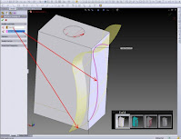
Swept Cut is a toolbar that functions to cut solid objects by adding a sketch aid as a rail or reference.
Sweep creates a base, boss, cut, or surface by moving a profile (section) along a path. A sweep can be simple or complex.
Swept Cut is a command in the Solidworks application that is used to cut 3D objects by sweeping the object (profile) against the path or sweep path that passes through it.
A Swept Cut needs a:
-Profile
-Path
-Guide curve
This Swept Cut command is the opposite command from Swept Boss / Base.
In the Solidworks application there are several commands that are used to convert 2D objects into 3D objects including
namely Extrude Boss / Base, Revolve Boss / Base and Swept Boss / Base commands.
The three commands have the opposite command or commands that have opposite functions, namely Extrude Cut, Revolve Cut and Swept Cut.
How to use the Swept Cut command.
The Swept Cut command is the opposite of the Swept Boss / Base command.
Its function is to cut 3D objects using a profile (object) that was swept across the specified path.
Swept Cut Command Location
We can find the Swept Cut command from the Command Manager or from the Menu Bar.
From Command Manager: Features> Swept Cut
From the Menu Bar: Insert> Cut> Sweep
We can't click the Swept Cut command while the sketch is active, so we must first exit the sketch before calling this command.
Select Profile and Path
After we click the Swept Cut command, a dialog box will appear on the left side of the work screen.
Look for the Profile and path fields.
Click the Profile field, then click the object to be sweep.
After that, click the Path field, then click the object that will be used as the Sweep path.
To end the Swept Cut process, click OK.
Comments Off

TEXT MTEXT LEADER QLEADER in AutoCAD

· Posted in , , ,

TEXT MTEXT LEADER QLEADER in AutoCAD
Dimension Text Edit is one of the commands in the autoCAD program that functions to change, copy, delete, modify text or dimensions both in the form of displacement, rotation and angle.
By using the Dimension text facility, edit or modify this dimension text. We can change the text in the dimensions that we make according to our wishes. Although text is created with the TEXT, MTEXT, LEADER, or QLEADER menu, it can be modified like an object from any other object.
We can also change the text properties from the Properties palette. we can also edit the contents of the text that has been created. Double click the text we want to edit. The Edit Text dialog box will appear for single line text, and a Multiline Text Editor will display for multiline text.
In editing text, we can also select the text type, right click and click Properties on the shortcut menu, then edit the text in the Properties palette.
Order of steps in editing text:
From the Modify menu on the autocad toolbar, select Object.
select Text. then select Edit.
select the text that we want to edit.
In the Text dialog box, type new text. then select OK.
Select any other text that you would like to edit, or press ENTER to end the process.
The difference between TEXT and MTEXT
Although they have the same function, which is both for creating text, TEXT and MTEXT have somewhat striking differences. Namely on TEXT it will produce writing with only one line, meaning that even though when writing with TEXT you make many lines at once, the result will still be one object per line. While on MTEXT it will produce writing with as many lines as you want, so the writing that you have made in lines will result in one object only.


Comments Off
Powered by Blogger.