Unigraphics : Sketch rectangle

In previous articles, we have learned to make the plane, the next step to make seketch drawing on the plane that we created earlier. This time we will learn to create a sketch 2d rectangle.
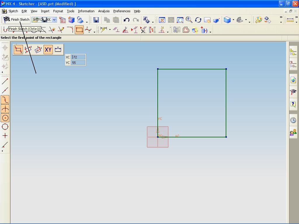
In making the rectangle are many steps that we can do, including making a rectangle by selecting the two diagonal corners. By using the cursor to determine the angle, this allows us to see the rectangular before it actually made.


Rectangles created in the XC-YC plane, YC, ZC, or XC-ZC.
The Rectangle option provides the option to make the curve and sketch
steps to create a rectangle:
1. Make the first corner; using Point Constructors or enter the input coordinates.
2. Making the second corner; by pulling the cursor to the desired location and click a mouse button or enter the coordinates.


We can make the sides of rectangular horizontal or vertical grid associated with the sketch.
For the rectangle side that is on a different orientation, create a line of Parallelogram.
In addition, to make a rectangle:
1. 1. Click Rectangle on the Sketch toolbar, or Tools, Sketch Entity, Rectangle.
2. . Click to place the first end of the rectangle, drag, and release when the rectangle according to the size and shape.


We can move and change the dimensions by clicking again the form we have created. (Click-click mode).
By dragging the cursor, the rectangle dimensions are dynamically displayed.
To change the size or shape of a rectangle:
In the sketch, pull to the side or upwards.
We can make a sketch of the segment to release when we are dragging it.
Click Tools, Sketch Settings, Remove Segment on Drag.


To change the properties of individual lines in the rectangle:
In an open sketch, select the line and edit the properties in the Line PropertyManager. In the sketch, select and edit the line in PropertyManager Line.

To exit the sketch, please click finish sketch.


Comments Off

Make a circle in some way

We can make a circle in some way, either by using the standard method for determining the center and radius. AutoCAD provides three other ways to draw a circle.
Draw a Circle Tangent to Other Objects
Tangent point is the point at which an object without touching other objects that intersect it. To create a circle that intersect with other objects, select the object and then specify the radius of the circle.


To create a circle tangent at three points
To make the circle tangent at three points, set to run the object is locked (OSNAP) for Tangent and three-point method to create a circle.


To draw a circle by specifying a center point and radius or diameter
To draw a circle by determining the center point and radius or diameter

From the Draw menu, select the Circle Center, Radius or the Center, Diameter.
Determine the center point.
Specify the radius or diameter.


Draw toolbar
Draw menu: Circle
Command line: circle

Determine the center point of circle or [3P (Three Points) / 2P (Two Points) / TTR (tan tan radius)]:
Specify a point or enter an option

Center Point Center Point
Draw a circle based on a center point and diameter or radius.

Determine the radius of circle or [Diameter]:
Specify a point, enter the value, enter d, or press ENTER

Comments Off

Solidworks - draft analysis

Using the settings in draft analysis, you can verify draft angles on model faces or you can examine angle changes within a face.
To apply a draft analysis to verify draft angles:
Open the model, then click Draft Analysis on the Mold Tools toolbar, or click Tools, Draft Analysis.
Under Analysis Parameters, do the following:
Select a planar face, a linear edge or an axis to indicate the Direction of Pull.
Note the draw direction. To change the draw direction, click Reverse Direction . You can also use the handle in the graphics area to reverse direction.

Enter a Draft Angle .
Click Face classification to conduct a face-based draft analysis.
If necessary, click the Find steep faces check box. Use steep faces when the model includes curved faces. Selecting Find steep faces displays faces that have a portion of the face with less angle than the specified draft angle to the direction of pull.
When you select Find steep faces, two additional categories, are displayed:
Positive steep faces
Negative steep faces

These categories function in the same manner as other face categories (positive draft, negative draft, and so on), but only apply to steep faces.
Click Calculate.(solidwork help)


-->


Comments Off

Unigraphics Extruded Body

If we edit the features that have been made with Extruded Body, we may see Extruded Body dialogs rather than current bar Extrude dialog bar.
In this case, we can do Editing.
Features that are made with Body Extruded
Extruded named, while creating a new feature called Extrude Extrude.
Both functions Extruded Body same as sweeping a profile, even though
the new Extrude is much more efficient, easier to use, and have more options.


Once we select a string for the section, we can select from the following methods:
Extruded Body Methods
Direction & Distance
Determine the location and thickness of the body in the unit distance along the specified direction. 
Trim to Face / Plane
Set limits by showing Face extrusion or datum on the target.
Trim Between Two Faces / Planes
Determine the extrusion limit by showing Two Faces / Planes from solid targets through which the extruded sketch.
Through Multiple Agency
Allows us to reduce the swept feature or from multiple target bodies.


Comments Off

Opening an Existing Part

In this activity, you will load an existing part into the work session.
Step 1: Open the intro_1 part.
Choose the Open icon. (File→Open)
The Open Part File dialog appears.
Check the current folder displayed in the Look in: field. If necessary, choose the parts folder.
Notice that there are no options to specify units (Inches and Millimeters) in the Open Part File dialog. The units of the parts were determined when they were created and cannot be changed within an active NX session. The units of a part can be converted
using a program called ug_convert_part.exe outside of the active session.
Select intro_1 in the file list box and choose OK to open the part (or double-click on the file name).
The Status Line displays information while the part is being retrieved as well as other information pertaining to the operation being performed.
Once the part is open the following actions occur:
• Options for viewing the contents of the file are available on the menu bar.
• Thegraphics window is now active, showing the model in the condition in which it was last saved.
• The title bar of the graphics window displays the name of the current work part and a status of Read Only. This means that changes may not be saved in this file.
A loaded part is only a copy of what is stored on disk. Any new work that you do is not permanent until the part is saved on disk.

Practical Applications of NX
Student Guide
January 2006
MT10050 — NX 4

Comments Off

Circle tangent to two objects

We can draw a circle or a circle with specified radius tangent to two objects or lines. Specify first point on the object tangent of circle: Select a circle, arc, or line Specify second point on the object tangent of circle: Select a circle, arc, or line Determine the radius of the circle: Sometimes more than one circle in accordance with the criteria that we set. AutoCAD makes a certain radius of the circle that intersect the closest point to the points selected. To make the circle tangent to two objects 1.Di Draw menu, click Circle Tan, Tan, Radius. Tangent command starts the object snap mode. 2.Select the first object to draw a circle tangent to. 3.Pilih second object to draw a circle tangent to. 4.Isi specify the radius of the circle. 5.Klik OK

Comments Off

Convert Entities Solidworks

We can create one or more curves in a sketch by projecting an edge, loop, face, curve, or adjust the sketch to sketch curves plane.Dalam convert an entity the steps we have to do is:
1.In this sketch open,
click on the model edge, loop, face, curve, external contour sketch, set of edges, or sets of curves.
2.Klik Convert Entities on the Sketch toolbar,
or click Tools, Sketch Tools, Convert Entities.
For On the Edge. The sketch can be made between the new sketch curves and entities. To Fixed Sketches can be made internally at the endpoints of the body so that it remains in a state sketch "fully defined". Internal relationship is not shown if we use the Display / Delete Relations. Release Fixed interesting relation with the end point.

Comments Off

Trimming body

This option allows us to cut / trim one or more of the body by using a face or datum. We can choose the body that we want to keep, and a body that will be trimmed in the form of trimming geometry. Modeling -> Insert -> Trim -> Trim Body or Feature Operation toolbar -> Trim Body Trim Body and Vector Direction Determine the direction of normal vector of the target body part that is stored. The vector points from the body of the saved. Trimming body Cylinder axis Vector direction pointed toward the cylinder axis Target body Results trim features body
    Trimming body Cylinder axis Vector direction pointing away from the axis cylinder Target body Results trim features body 

Comments Off
Powered by Blogger.