We can make a circle in some way, either by using the standard method for determining the center and radius. AutoCAD provides three other ways to draw a circle.
Draw a Circle Tangent to Other Objects
Tangent point is the point at which an object without touching other objects that intersect it. To create a circle that intersect with other objects, select the object and then specify the radius of the circle.
To create a circle tangent at three points
To make the circle tangent at three points, set to run the object is locked (OSNAP) for Tangent and three-point method to create a circle.
To draw a circle by specifying a center point and radius or diameter
To draw a circle by determining the center point and radius or diameter
From the Draw menu, select the Circle Center, Radius or the Center, Diameter.
Determine the center point.
Specify the radius or diameter.
Draw toolbar
Draw menu: Circle
Command line: circle
Determine the center point of circle or [3P (Three Points) / 2P (Two Points) / TTR (tan tan radius)]:
Specify a point or enter an option
Center Point Center Point
Draw a circle based on a center point and diameter or radius.
Determine the radius of circle or [Diameter]:
Specify a point, enter the value, enter d, or press ENTER
Radius Finger
Defining the radius of the circle.
Enter a value, or set point.
The distance between the point and center point determines the radius of the circle.
Diameter Diameter
Draw a circle using the center point and a certain distance to diameter.
Determine the diameter of the circle
Determining a point
enter the value, or press ENTER
3P (Three Points) 3P (Three Points)
Draw a circle based on three points on the circumference.
Specify first point on the circle:
Specify a point (1)
Determine the point on the second circle: Specify a point (2)
Determine the point on the third circle: Specify a point (3)
.......................................
SOLIDWORK, UNIGRAPHICS, AUTOCAD, ILLUSTRATOR, PHOTOSHOP
Start making simple 3D
We'll start making this 3D with more detail and complete again with the start of creating a new part.
Click the New button on the Standard toolbar.
New SolidWorks Document dialog box will appear.
Click Part.
Click OK
Next determine the plane
Determine the plane or the area that we want to make pictures ..... top, bottom, right or left
Next we create a sketch, for now we will make the box, then
Click Rectangle on the Sketch toolbar.
The Rectangle PropertyManager open in the left window.
Move the pointer in the workspace.
Click to place the starting point of the image.
Move the mouse and see a dynamic preview to follow the pointer.
Release the mouse and click on PropertyManager to complete the rectangle.
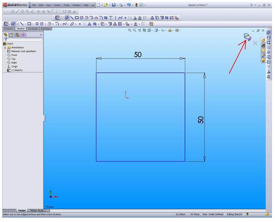
Now add the desired dimensions.
Click Smart Dimension on the Sketch toolbar.
Select the box that we are drawing.
Notice the preview box dimensions.
Move the pointer to where we want to give dimension and click to add dimension.
In the Modify box, click on the graph area.
Click Extrude 2D sketches to create 3D blocks.
Click Sketch on the Sketch toolbar to get out of Sketch.
The settings for extrusion appeared in PropertyManager in the left pane.
In PropertyManager, under Direction 1:
Select End Condition Blind ins.
Do not forget to save
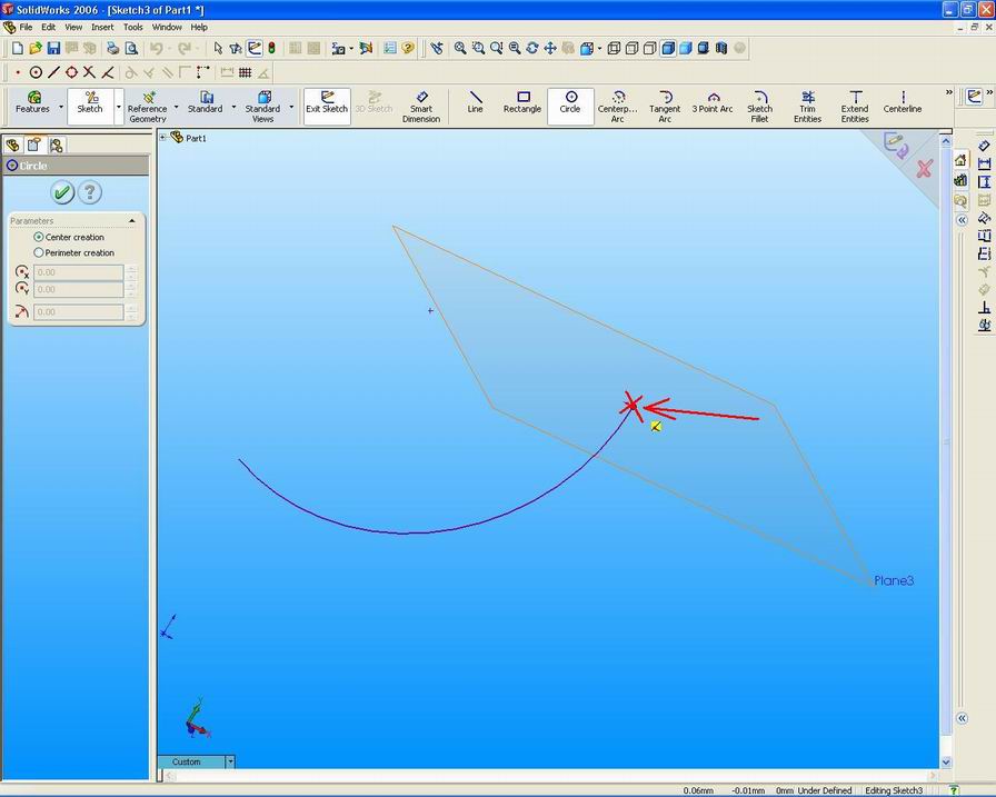
Comments Off
Make a sketch rectangle UniGRAPHICS
In making the rectangle are many steps that we can do, including making a rectangle by selecting the two diagonal corners. By using the cursor to determine the angle, this allows us to see the rectangular before it actually made.
Rectangles created in the XC-YC plane, YC, ZC, or XC-ZC.
The Rectangle option provides the option to make the curve and sketch
steps to create a rectangle:
1. Make the first corner; using Point Constructors or enter the input coordinates.
2. Making the second corner; by pulling the cursor to the desired location and click a mouse button or enter the coordinates.
We can make the sides of rectangular horizontal or vertical grid associated with the sketch.
For the rectangle side that is on a different orientation, create a line of Parallelogram.
In addition, to make a rectangle:
1. Click Rectangle on the Sketch toolbar, or Tools, Sketch Entity, Rectangle.
2. Click to place the first end of the rectangle, drag, and release when the rectangle according to the size and shape.
Comments Off
Solidwork : Creating a new plane with arc or curve
The first step we have to do is click on the toolbar Plane Geometry references, or click Insert, Reference Geometry, Plane.
The PropertyManager Plane will appear.
In the selection, select the type of plane that we want to create and the items to make a plane:
For the Normal Curve.
Create a plane through point and perpendicular to the edge or curve.
Select the edges or curves, and dots.
Select Set the origin on the curve of a check box to the place of origin on the curve, the default is to place the origin point
We only select the curve to create a new plane. Plane perpendicular to the end of the curve. The selected items will appear in the Reference Entities box. A preview of the new plane appears in the graph area. Click OK to create the plane. new plane appears in the graphics area and te rdaftar in FeatureManager design tree. To cancel the transaction, click cancel. To create a plane, click save in PropertyManager Plane will be displayed.
Comments Off
Powered by Blogger.
Popular Posts
-
We can draw a circle or a circle with specified radius tangent to two objects or lines. Specify first point on the object tangent of circl...
-
Split Line tools to project entities such as sketches, solid, surface, face, plane, or surface spline to surfaces, or curved or planar...
-
Set the initial conditions to extrude cut feature with offset As we embark on the plane cut extrude the sketch plane offset from there. ...
-
We can also determine the dimensions of angle by determining the angle point and end point. When we make a dimension, we can modify the c...
-
In the Solidworks facility helps us create a 3D solid, namely surface knit. Knit Surface tool is used to combine two or more faces or ...
-
The first step we have to do is click on the toolbar Plane Geometry references, or click Insert, Reference Geometry, Plane. The PropertyM...
-
Step 1. Create a circle with a diameter of 85 sketches, on the top plane Step 2. Boss-Extrude1, to create a pedestal table. Click ...
-
We can create one or more curves in a sketch by projecting an edge, loop, face, curve, or adjust the sketch to sketch curves plane.Dalam ...
-
This option allows us to cut / trim one or more of the body by using a face or datum. We can choose the body that we want to keep, and a b...
-
We will start using the existing facilities in Unigraphics to draw 3dimensi. One of the facilities we will use to draw 3d is Extrude Use...
Categories
- 3d (1)
- Array (1)
- arrowsheads (1)
- AutoCAD (1)
- combine (1)
- commands (1)
- create a new part (1)
- Create a Polar (1)
- Creating (1)
- customize (1)
- cylinder (1)
- datum (1)
- dimension (1)
- Dimensioning (1)
- dockable (1)
- down (1)
- drop (1)
- dwg (1)
- dxf (1)
- entity (1)
- export (1)
- Features (1)
- fixed (1)
- guide curve (1)
- Hole (1)
- insert (1)
- LEADER (1)
- learning (1)
- loft (1)
- main (1)
- manager (1)
- menu (1)
- method (1)
- modeling (1)
- modify (1)
- MTEXT (1)
- NX (1)
- objects (1)
- parametrics (1)
- path (1)
- pattern (1)
- plane unigraphics (1)
- profile (1)
- properties (1)
- QLEADER (1)
- relations (1)
- relative (1)
- sketch (2)
- sketches (1)
- Sketching (1)
- Solid Object (1)
- Solidworks (1)
- solidworks tutorials (1)
- style (1)
- substract (1)
- sweep (1)
- swept cut (1)
- symbol (1)
- TEXT (1)
- the Revolve (1)
- third mouse button (1)
- tool palletes (1)
- toolbars (1)
- UG (1)