Draft Overview solidwork

The draft features a 3d application to make the slope of the surface using a certain angle to a selected surface in 3D modeling. We can enter the draft in part that we want. we can apply the concept of the draft to a solid or surface model. We can determine the type of drafting with the following methods: -Neutral plane Parting line- Draft-Step Neutral Plane Draft We can make a feature taper model chosen by using Plane neutral and face a certain angle, to determine the direction of making the mold. We also can apply the concept of angle as part of the base extrusion, boss, or cut. Neutral Plane To make draft Click the Draft button in the toolbar features, or Insert, Features, Draft. In Property Manager: Select Neutral Plane in the draft. In the Draft Angle, set the value to degrees. Draft angle measured perpendicular to the plane of neutral. Select a face or plane to plane Neutral. If necessary, select Reverse obliquity draft in the opposite direction. Select the faces to the draft in the area of graphics for the Faces, which will be made. All Faces. The concept of all face is extruded from the neutral plane. Inner Faces. The concept of all parts of a face is extruded from the neutral plane. Outer Faces. The concept of all the outer face neutral plane. Detailed click Preview to preview the draft. Click OK to create the draft. Using the Neutral Plane as a type of draft, we can design some outer face, all face the outside, some face in all inner faces, faces a tangent, or a combination of both inner and outer faces faces. In Property Manager, under a Face, select Face value propagation. Face Propagation Selection in the Graphics Area Draft Results None. Only a selected face in the draft. Face above is used as a Neutral Plane in all instances. Along Tangent. Extend the draft to all face that intersect with the selected face. Face out, including one of the face that we choose the Extrude boss. All face. Draft all face in addition to the neutral plane and extruded from the neutral plane. inner faces include face on three Ekstrud boss. Inner Faces. Draft all the inner faces are extruded from the neutral plane. Outer Faces. Draft all the outer faces outwardly neutral plane.

Comments Off

UNIGRAPHICS make a line with Offset

This option allows us to create a line in relation to the reference line that we have set.
Location can be based on absolute or work in a coordinate system.
If we choose the offset, we select a line that was created as a baseline (reference site) to make a line offset.
This is useful if we want to more quickly make a lot of lines where each line offset is made from the previous line.
 
Steps - steps that must be done to make a line with an offset:
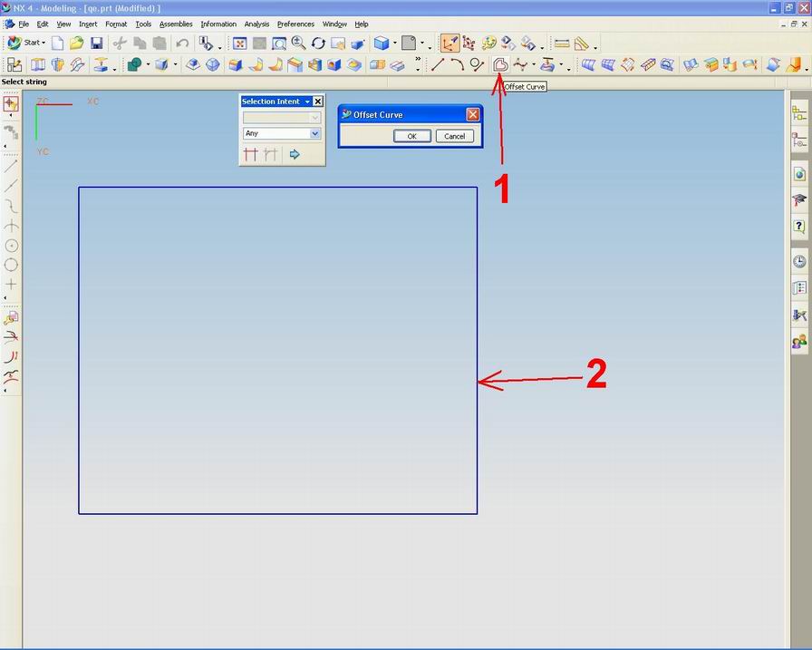
1.Select menu offset curve
2.Select the object that will be offset 3.klik OK on the tool offset curve 4.tentukan distance you want to create 5.klik OK to terminate the process

Comments Off

Create Fillets, AutoCAD

Filleting connect two objects with ease for a certain radius. An angle is called the fillet and the outer corner is called a round; We can make inside and outside fillet fillet fillet use in AutoCAD. We can do the fillets on the object: -Arc -Circle -Ellipse -arc -Line -Polylines -Splines -Xlines Fillet Using an easy method for creating an arc with a certain radius that is tangent to two objects selected. Fillets can be used to collect all the angles the polyline using a single command. If the two objects in the fillets are on the same layer, the fillet arc is at the same layer. If you are on layers of different, will affect layer object properties including color and linetype. Set the Radius Fillet fillet radius is the radius of the arc that connects the object fillets. If we set the fillet radius with the number 0, the object is trimmed filleted or extended until they meet (sharp), there is no radius are made. Trim and Extend Objects Filleted Filleted Object Trim and Extend We can use the Trim option to determine whether The selected objects are trimmed or extended to the endpoints of the arc. By default, all objects except the circle, filled ellipse, closed polylines, and splines can be in the fillet (trimmed or expanded). Depending on the location we specify, more than one fillet can be made between the selected object.

Comments Off

make 3d

On this occasion we will start using the existing facilities in Unigraphics to draw 3dimensi. One of the facilities we will use to draw 3d is Extrude Use this facility to create a body with sweeping 2D or 3D profile curve, edge, face, sketch or feature curve is linear distance in a certain direction. Boolean option allows us to create, together, cut the object that we make. The steps create a simple extrusion using a sketch 1. Select the Extrude option, a dialog bar that displays the Extrude dialog. 2. Setting Selection of Intent to Add Connected. 3. To select a set of strings profile curve or edge, or a sketch. Preview display features extruded using a default value. 4. Limit Pull the handle, or use the distance field in the dialog box or in a dynamic input to the desired size of the extrusion. 5. Click OK. Recommended extrusion has been made

Comments Off
Powered by Blogger.