Convert Entities Solidworks

We can create one or more curves in a sketch by projecting an edge, loop, face, curve, or adjust the sketch to sketch curves plane.Dalam convert an entity the steps we have to do is:
1.In this sketch open,
click on the model edge, loop, face, curve, external contour sketch, set of edges, or sets of curves.
2.Klik Convert Entities on the Sketch toolbar,
or click Tools, Sketch Tools, Convert Entities.
For On the Edge. The sketch can be made between the new sketch curves and entities. To Fixed Sketches can be made internally at the endpoints of the body so that it remains in a state sketch "fully defined". Internal relationship is not shown if we use the Display / Delete Relations. Release Fixed interesting relation with the end point.

Comments Off

Trimming body

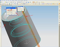
This option allows us to cut / trim one or more of the body by using a face or datum. We can choose the body that we want to keep, and a body that will be trimmed in the form of trimming geometry. Modeling -> Insert -> Trim -> Trim Body or Feature Operation toolbar -> Trim Body Trim Body and Vector Direction Determine the direction of normal vector of the target body part that is stored. The vector points from the body of the saved. Trimming body Cylinder axis Vector direction pointed toward the cylinder axis Target body Results trim features body
    Trimming body Cylinder axis Vector direction pointing away from the axis cylinder Target body Results trim features body 

Comments Off

Mirror Autocad

Menu mirror creates a mirror image of an object. This menu is very useful to create symmetrical objects because we can quickly draw half the object and then reflects the image the whole objects. we flip the object on the axis, called the mirror line to create a mirror image. To determine the line of the mirror while, we enter two points. we can choose whether to remove or retain the objects asli.Mirroring work in parallel to the plane XY of the current UCS.
If we are to mirror the text, attributes, and attribute definitions,
results will be inverted or reversed in mirror image.
To prevent this from happening, set MIRRTEXT system variable to 0 (off).
Results text will then have the same alignment and justification as before reflecting.
By default, MIRRTEXT inactive.
To make a mirror object:
1. From the Modify menu, select Mirror. 2. Select the object to the mirror. 3. Specify the first point of mirror line. 4. Specify the second point. 5. Press ENTER to retain the original object, or enter y to delete the object in a mirror.

Comments Off

Surface - EXTEND

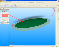
With the menu extend surface, we can extend the surface by selecting the edge, some edge, or face. To make the surface extends: Click the Extended surface on the toolbar or click Insert Surface, surface, Extend. In the Property Manager: Under Edges / Faces to Extend, select one or more sides or face as desired. If we choose the edge, extending surface extends along the field edge. If we choose the face, extending surface extends along all sides of the face except those connected to the other face. we can make the surface extended to face tangent by clicking on the callout the which appears only if we choose the edge.
Select type of End Condition: If we choose Distance. Extend surface will correspond to the distance that we specify. If we choose the Up-to-point. Extend will surface to the point that we choose in the graphics for the Vertex. If we choose Up to surface. Extend will surface to surface or face that we choose in the graphics area to surface / Face.
  Select Type Extensions: Same surface. Extend surface along the surface geometry. Linear. Extend surface tangent to the original surface along the edge.

Comments Off
Powered by Blogger.