Unigraphics of CAD


We can design a autocad drawing 3D with assistance to facilitate and speed up our design.
This import command allows us to choose the type of geometric constraints that apply automatically to our sketch.
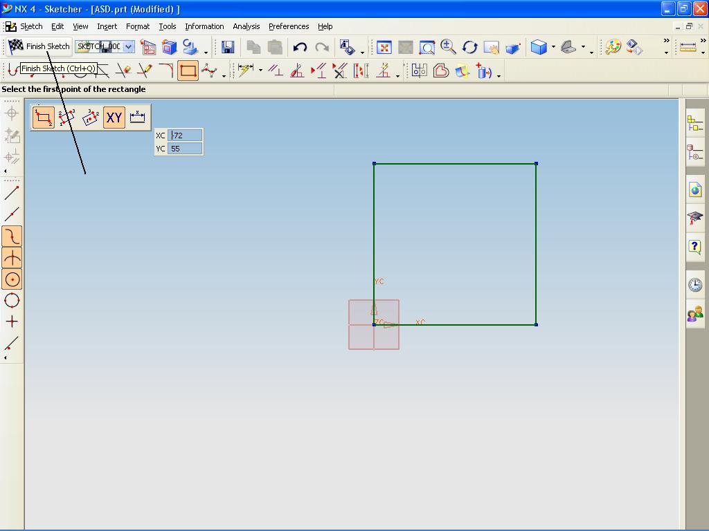
NX geometry analysis in an active sketch will implement the chosen constraints.
This function can be very useful when we add to the sketch geometry active,
especially if the geometry is imported from the system in the form of CAD (DWG)


Comments Off

AutoCAD Hatch

This pattern is used to distinguish the components or to indicate the materials that make up an object. 
We can use predefined hatch pattern, determine the pattern of simple lines using the current linetype,
or create a hatch pattern is more complex.
We can also create a gradient fill, which use transitions between shades of one color or between two colors.


We can drag and drop hatches from the tool palette or use a dialog box with additional options.

We can choose among several methods for determining the boundaries of hatch,
and we can control whether the hatch automatically adjust when boundary changes are made.
To reduce the file size, hatch patterns defined in the database image as a single graphic object.


In AutoCAD, we can use several methods to add hatch patterns to our image.
Use a palette toolst when we need the speed and convenience.


With the Tool Palette window open, you can click right to access the Tool Properties dialog box from the shortcut menu.
This dialog box contains several options hatch patterns are also available through BHATCH.
Here we can determine the scale and spacing for hatch pattern.
In AutoCAD there are more than 50 industry-standard hatch patterns that we can use to distinguish the component object.
AutoCAD has a hatch pattern 14 which in accordance with ISO (International Standards Organization) standard.
biila we choose the ISO pattern, we can determine the width of a pen, which determines lineweight in the pattern.
When we make a hatch, by default hatch boundary drawn on the back hatch.
This makes it easier to see and select a hatch boundary.
We also can set your own hatch pattern using a linetype by filling out the dialog box,
or we can create more complex hatch patterns.

To create a hatch (shaded) in autocad

initial step that must be done is on the Draw menu, click Hatch.
In the Boundary Hatch and Fill dialog box, click Pick Points.
Determine the point in every area of the image that we want to create a hatch, and then press ENTER.
In the Boundary Hatch, Fill dialog box, Hatch tab, and swatch box, make sure that the sample pattern is the pattern we want to use.
To change the pattern, select another pattern from the Pattern list.
To see how the hatch pattern that we created, click the [...] button next to the Pattern.
Click OK when finished to see the preview.


-------------------------------------------------------------------------------
SOLIDWORK, UNIGRAPHICS,  AUTOCAD,    ILLUSTRATOR,  PHOTOSHOP

Comments Off

SOLIDWORKS : Easy way to learn 3d solidwork

Now  We will create a rectangle boss who refers to the previous discussion.
The first step to open the file before, then
Create a sketch for rec boss.
Click Extruded Boss / Base on the Features toolbar.
Select the top face on the object.
Top Click on the Standard Views toolbar.
Click Rectangle on the Sketch toolbar.
Move the pointer over the layout.
Begin drawing a rectangle
Click to place the end of the rectangle.
Move the pointer to create a rectangle.
Remove the pointer and click on PropertyManager to complete the rectangle.


Click Smart Dimension on the toolbar / Relations toolbar.
Select the rectangle.
Move the pointer on the rectangle and click to place the dimension.
Modification of the contents of the box and then click the desired dimension in the graphics area.


Now we make a sketch has been completed, Extrude the sketch to make the boss rec.
Click on the toolbar Sketch Sketch.
Click Trimetric on the Standard Views toolbar for a better view.
In PropertyManager, under Direction 1, set Depth to 15.
Click OK


Comments Off

Unigraphics : Sketch rectangle

In previous articles, we have learned to make the plane, the next step to make seketch drawing on the plane that we created earlier. This time we will learn to create a sketch 2d rectangle.
In making the rectangle are many steps that we can do, including making a rectangle by selecting the two diagonal corners. By using the cursor to determine the angle, this allows us to see the rectangular before it actually made.


Rectangles created in the XC-YC plane, YC, ZC, or XC-ZC.
The Rectangle option provides the option to make the curve and sketch
steps to create a rectangle:
1. Make the first corner; using Point Constructors or enter the input coordinates.
2. Making the second corner; by pulling the cursor to the desired location and click a mouse button or enter the coordinates.


We can make the sides of rectangular horizontal or vertical grid associated with the sketch.
For the rectangle side that is on a different orientation, create a line of Parallelogram.
In addition, to make a rectangle:
1. 1. Click Rectangle on the Sketch toolbar, or Tools, Sketch Entity, Rectangle.
2. . Click to place the first end of the rectangle, drag, and release when the rectangle according to the size and shape.


We can move and change the dimensions by clicking again the form we have created. (Click-click mode).
By dragging the cursor, the rectangle dimensions are dynamically displayed.
To change the size or shape of a rectangle:
In the sketch, pull to the side or upwards.
We can make a sketch of the segment to release when we are dragging it.
Click Tools, Sketch Settings, Remove Segment on Drag.


To change the properties of individual lines in the rectangle:
In an open sketch, select the line and edit the properties in the Line PropertyManager. In the sketch, select and edit the line in PropertyManager Line.

To exit the sketch, please click finish sketch.


Comments Off
Powered by Blogger.