
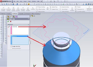
Split Line tools to project entities such as sketches, solid, surface, face, plane, or surface spline to surfaces, or curved or planar. It divides the selected face into several separate face. we can divide the curve on some solid body with a single command. We can make a line following divisions: Projection. Projection sketch on the surface. We can divide the pattern line features created using projection curves. We can make use of text split line sketch. This is useful for making items such as decals. Silhouette. Make the split line on the cylinder. Intersection. Splits face with intersecting solid, surface, face, plane, or spline surface. When we make a line break with an open profile sketch, sketch must span at least tw
o sides of the model
 .
.
Creating Lines Split When we made the split lines, edges do not change that can be reused in the downstream and changed the update feature edges. In this model we insert line splits at the front face as the last item in the FeatureManager design tree. If we change the order Line1 Split follow Extrude1 features, models defend downstream chamfer and fillet.

To create a projection split line:Click Split Line (Curves toolbar) or Insert, Curve, Split Line. In the PropertyManager, under Type Split, select Projection. Under Selection, click: A sketch for Sketch for the Project. We can choose some of the contours of the same sketches to share. face-face to project sketches for face to Split. One way to project the split line in only one direction.Click OK. To create a split line silhouette:Click Split Line (Curves toolbar) or Insert, Curve, Split Line. In the PropertyManager, under Type Split, click Silhouette. In Selection: Select the plane to the project through the silhouette of the model (the outside) for Direction of Pull. Select the face to face project for the plane to Split. face can not be planar. Set Angle to create a draft angle.Click OK. To create a line of cleavage junction:Click Split Line (Curves toolbar) or Insert, Curve, Split Line. In the PropertyManager, under Type Split, select Intersection. In Selection: Choose a splitting tool (solid cut, surface, face, plane, or surface splines) for Non Separates / face / Planes.Click on the face / body to Split, and select the target face or body that projected splitting tool.Click OK


