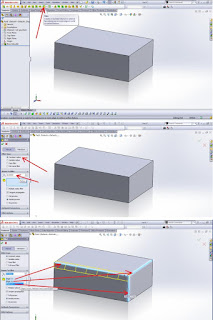
CIRCULAR ARRAY 3D Solidworks

Array is a repeating pattern of the selected features. we can create a linear pattern, a circular pattern, a pattern driven curve, fill patterns, or use sketch points or coordinate tables to create a pattern. We can choose the option Visual Properties in the Property Manager. With parts of the multi-body, you can use a pattern or a pattern or feature mirror to mirror some of the bodies in the same document. For Linear pattern, select the feature, then specify the direction, linear distance, and the total number of cases. For Pattern Circular, select the features and benefits as the center or axis of rotation, then specify: The number of cases and the total angle at which to create the pattern. For Curve Driven Pattern, select the features and advantages or segments sketch to pattern features. Then you can determine the type of curve, curve method, and the method of alignment. For Patterns Sketch, choose where to fill the superior features by sketching points on the model's face. For Table pattern, add or retrieve previously made X-Y coordinates for the filling of excellent features on the model's face. For Pattern Fill, fill the area defined by a pattern or cut features defined configurations. For Mirror Features, select a feature to copy and planes around which to mirror them. If you choose a planar face on the model, you mirror the entire model of the selected face. 
1. Draw a line to the reference axis
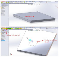
2. Make a feature that will be in the array, make an example extrude cut like
on picture
3. Select the Array ==> Circullar
4. Fill the parameters axis by axis sketch that has been made - Fill in the amount of features we wanted - click Equal spacing (if we wanted the same distance) - Select a feature that will be in the array (extruded cut has been made) - OK (click the check the color green).
Comments Off

Curve Driven Pattern Solidworks tutorial

1. Make a sketch curve (pattern) which is the reference Pattern / Array.
Example: Create a spline
2. Make a Feature that will be in the pattern. Example: Extrude cut
3. Select the Pattern ==> Curve Driven Pattern - Select Sketch has been created to fill Direction 1 - Fill pattern desired amount - Click Equal spacing (to make the same distance along the curve) or - Fill D1 = to make a suitable distance our desires - Select Feature that will be in pattern (Extrude cut)
4. OK (click the check mark Green color)

The Curve Drive Pattern PropertyManager appears when you create a new curve driven pattern feature, or when you edit an existing curve driven pattern feature. The PropertyManager controls the following properties: Direction 1 Pattern Direction. Select a curve, edge, sketch entity, or select a sketch from the FeatureManager to use as the path for the pattern. If necessary, click Reverse Direction to change the direction of the pattern. The example below uses the upper edge of the model as the Pattern Direction for Direction 1. Number of Instances . Set a value for the number of instances of the seed feature in the pattern. Equal spacing. Sets equal spacing between each pattern instance. The separation between instances depends on the curve selected for Pattern Direction and on the Curve method. Equal spacing check box cleared Equal spacing check box selected Spacing (Available if you do not select Equal spacing). Set a value for the distance between pattern instances along the curve. The distance between the curve and the Features to Pattern is measured normal to the curve. Curve method. Defines the direction of the pattern by transforming how you use the curve selected for Pattern Direction. Select one of the following: Transform curve. The delta X and delta Y distances from the origin of the selected curve to the seed feature are maintained for each instance. Offset curve. The normal distance from the origin of the selected curve to the seed feature is maintained for each instance. Alignment method. Select one of the following: Tangent to curve. Aligns each instance tangent to the curve selected for Pattern Direction. Align to seed. Aligns each instance to match the original alignment of the seed feature. of Curve method and Alignment method selections. Face normal (For 3D curves only). Select the face on which the 3D curve lies to create the curve driven pattern.

Comments Off

Solidworks Tutorials Fillet Setback

Creates a smooth transition where fillet edges meet. Setback fillets. Defines a setback distance from a vertex at which the fillets start to blend The Fillet PropertyManager appears when you create a new fillet feature, or when you edit an existing fillet feature. The PropertyManager displays the appropriate options based on the type of fillet you create. The PropertyManager remembers its last used state. Setback fillet shown with Full preview , and with the same setback Distance of 12mm applied to all three edges. Setback fillet shown with Full preview , and with a different setback Distance applied to all three edges. 
FILLET with setback
Process sequence:
1. Select the Fillet feature
2. Select Constan radius and the content of the desired radius
3. Select the desired edge
4. Click the menu setback
5. Define the corner of the selected edge meeting
6. Determine the value setback (setback if the same value can click Set All or may also different value for masing2 side edge). In order to more clearly see the picture.

Comments Off

Tutorial Unigraphics Creating a positioned 2D sketch

Creating a positioned sketch Unigraphics enables you to define explicitly the position of the sketch absolute axis. This offers the following advantages: When the geometry of the part evolves and the associated position of the sketch changes, the shape of the sketched profile (2D geometry of the sketch) remains unchanged (even if the sketched profile is under-constrained). Creating a positioned sketch also ensures associativity with the 3D geometry. Open the Positioned_sketch.CATPart document. You will now create a positioned sketch that will enable you to design the retaining bracket for this part. You will position the sketch absolute axis as follows: its origin will be on the axis of revolution, its horizontal (H) direction will be parallel to the flat face, its vertical (V) direction will be normal to the flat face. Make sure the Reference field is active, and select the blue surface (Shaft.1). The Sketch Positioning dialog box is updated: the Reference field now indicates the reference plane. Also, the Type fields of the Origin and Orientation areas are activated and the Implicit mode is pre-selected. Steps by steps tutorial : Open the file that will be modified. Modeling Run, application and create a layer Iayer work. Create a new sketch. - Select Sketch. - Click on the name of the sketch - Choose the face parts to be modified. By selecting the face on the top, the positive direction will lead XC pad away from the pointed end. Select OK. If our view is not visible, choose File-> Close-> Reopen Selected Parts. select Profile Make sure the list. Constraints to be set to All in Sketch On, Constraint Type is set to All, and Show Constraints set to explicit. There should be one horizontal and one vertical constraint Select Cancel. Constrained sketches. In the design, size must be controlled by determining the length of the horizontally and vertically. Select Dimensions. Select the horizontal line and place the dimension. Change the value and Enter.

Comments Off
Powered by Blogger.