Tutorial Delete Face - Fill Tangen Solidworks
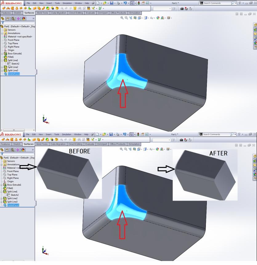
1. Open the file with a face that has been split, select the delete face
2. Fill Selection with a face like a picture, on select Delete an Option
fill and check tangent fill selection
3. Click OK
4. The result can be seen from the pictures before and after the process delete face.

Delete Face
Deletes a face from a surface body, or deletes one or more faces from a solid body to create surfaces...Deletes a face from a surface body or solid body and automatically patches and trims the body...Deletes faces and generates a single face to close any gap
Parts and Features > Features
Mid Surface
You can either add new face pairs, delete existing ones, or update face pairs...Select a set in Face Pairs and press Delete
Parts and Features > Features
Recognizing Features Interactively
If you want to delete one or more faces, click Delete Faces...If you delete faces that are necessary for previously recognized features, FeatureWorks will not be able to recreate those features
Parts and Features > Features
Choose Option
From the Delete Face PropertyManager, you can select one or more faces on the solid model to create surfaces
Import Diagnostics PropertyManager
If a face has too many faults to repair, you can delete the face and insert a new face in the gap
Import and Export > Import Diagnostics Overview
Mold Design Tools Overview
Deletes a face from a surface body or solid body and automatically patches and trims the body...Deletes faces and generates a single face to close any gap
Mold Design|SOLIDWORKS Fundamentals > Industry-specific Design Tools|Mold Design Tools Overview
Tool and Die Design Tools Overview
Deletes a face from a surface body, or deletes one or more faces from a solid body to create surfaces...Deletes a face from a surface body or solid body and automatically patches and trims the body...Deletes faces and generates a single face to close any gap
SOLIDWORKS Fundamentals > Industry-specific Design Tools
Delete Faces Example
The following illustrates a good use of Delete Faces...Delete the filleted faces, then recognize the rest of the features in the model...If you delete faces that are necessary for previously recognized features, FeatureWorks will not be able to recreate those features
Parts and Features > Features
Hints for Interactive Feature Recognition
Use Delete Face(s) to remove complex or unwanted faces...If you delete faces that are necessary for previously recognized features, FeatureWorks will not be able to recreate those features
Parts and Features > Features
Extruding Surfaces from a 2D or 3D Face
To remove the faces defining the extrude from the model after extruding, click Delete original faces...The resulting model is hollow where the face was deleted
Parts and Features > Features.