Swept Cut Profile Path Guide Curve Solidworks

· Posted in , , ,

Swept Cut Solidworks
Swept Cut is a toolbar that functions to cut solid objects by adding a sketch aid as a rail or reference.
Sweep creates a base, boss, cut, or surface by moving a profile (section) along a path. A sweep can be simple or complex.
Swept Cut is a command in the Solidworks application that is used to cut 3D objects by sweeping the object (profile) against the path or sweep path that passes through it.
A Swept Cut needs a:
-Profile
-Path
-Guide curve
This Swept Cut command is the opposite command from Swept Boss / Base.
In the Solidworks application there are several commands that are used to convert 2D objects into 3D objects including
namely Extrude Boss / Base, Revolve Boss / Base and Swept Boss / Base commands.
The three commands have the opposite command or commands that have opposite functions, namely Extrude Cut, Revolve Cut and Swept Cut.
How to use the Swept Cut command.
The Swept Cut command is the opposite of the Swept Boss / Base command.
Its function is to cut 3D objects using a profile (object) that was swept across the specified path.
Swept Cut Command Location
We can find the Swept Cut command from the Command Manager or from the Menu Bar.
From Command Manager: Features> Swept Cut
From the Menu Bar: Insert> Cut> Sweep
We can't click the Swept Cut command while the sketch is active, so we must first exit the sketch before calling this command.
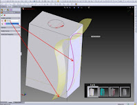
Select Profile and Path
After we click the Swept Cut command, a dialog box will appear on the left side of the work screen.
Look for the Profile and path fields.
Click the Profile field, then click the object to be sweep.
After that, click the Path field, then click the object that will be used as the Sweep path.
To end the Swept Cut process, click OK.
Comments Off

TEXT MTEXT LEADER QLEADER in AutoCAD

· Posted in , , ,

TEXT MTEXT LEADER QLEADER in AutoCAD
Dimension Text Edit is one of the commands in the autoCAD program that functions to change, copy, delete, modify text or dimensions both in the form of displacement, rotation and angle.
By using the Dimension text facility, edit or modify this dimension text. We can change the text in the dimensions that we make according to our wishes. Although text is created with the TEXT, MTEXT, LEADER, or QLEADER menu, it can be modified like an object from any other object.
We can also change the text properties from the Properties palette. we can also edit the contents of the text that has been created. Double click the text we want to edit. The Edit Text dialog box will appear for single line text, and a Multiline Text Editor will display for multiline text.
In editing text, we can also select the text type, right click and click Properties on the shortcut menu, then edit the text in the Properties palette.
Order of steps in editing text:
From the Modify menu on the autocad toolbar, select Object.
select Text. then select Edit.
select the text that we want to edit.
In the Text dialog box, type new text. then select OK.
Select any other text that you would like to edit, or press ENTER to end the process.
The difference between TEXT and MTEXT
Although they have the same function, which is both for creating text, TEXT and MTEXT have somewhat striking differences. Namely on TEXT it will produce writing with only one line, meaning that even though when writing with TEXT you make many lines at once, the result will still be one object per line. While on MTEXT it will produce writing with as many lines as you want, so the writing that you have made in lines will result in one object only.


Comments Off

Learn to make Solid Object modeling using the Loft solidworks method

Solid Object Modeling using the Loft method.
Example: Making a solid cylinder with R = 50 mm and a length of 200 mm.
1. Click the New icon, part icon, to create a new part.
2. Click the front icon, and the 2D sketch icon, so that we can activate the sketch tool.
3. Click the circle icon, and then from the origin we create a circle with R = 50 mm
4. Click the 2D sketch icon so that the sketch tool is inactive.
5. Click the isometric icon so that we get the circle sketch image in the isometric projection.
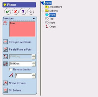
6. On the menu bar line, Click Insert, Reference Geometry, Plane. So that the Plane dialog box will be active as follows:


8. From the Plane box above, we click the plane, so that the right side will activate the Feature Manager Design Tree (FMDT). In FMDT, we click front
So that in the Selection section there will be Front text. After that, type 2000 mm and check the Reverse direction box.
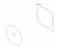
9.Click the plane1 icon and the 2D sketch icon so that we can activate the sketch tool.
10.Click the circle icon, and then from the origin create a circle with R = 50 mm.
11. Then click 2D sketch so that the sketch tool is inactive. So that we get an image like the following:


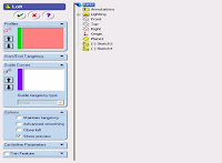
12. Click the loft icon or on the menu bar click Insert, base, Loft. so that the Loft dialog box will be 
active as follows:


13. From the Loft dialog box above, click loft so that the right side will activate the Feature Manager Design Tree (FMDT). On FMDT click 3 and sketch 4, so that both sketches will be read in the group profile.
14. After the above process is complete, click the checklist so that we get a solid cylinder from the loft 
method.


Comments Off

Using Parametrics in Sketches Solidworks Tutorials

Sketching in SOLIDWORKS is the basis for creating features. Features are the basis for creating parts, which can be put together into assemblies. Sketch entities can also be added to drawings. What separates parametric CAD tools from simple 2D drawing programs is the intelligence that you can build in to a parametric sketch. In this tutorial, you learn some of the power that parametrics can provide in both structured using actual dimensions and unstructured changes. 1. Open a new SolidWorks document by clicking the New toolbar button or by choosing File, New. 2. From the list of templates, select a new part template, either inch or millimeter. 3. Press the Spacebar on the keyboard to open the View Orientation dialog box, and double click the Front view. 4. Right-click the Front plane in the FeatureManager, or whatever the first plane listed is, and select Sketch. 5. Click the View menu, and make sure the Sketch Relations item is depressed. This shows small icons on the screen to indicate when parametric relations are created between sketch entities. 6. Click the Circle from the Sketch toolbar, choose Tools, Sketch Entities, Circle. 7. Sketch a circle centered on the Origin. With the Circle tool activated, click the cursor at the Origin in the graphics area. The Origin is the asterisk at the intersection of the long vertical red arrow and the short horizontal red arrow. After clicking the first point, which represents the center of the circle, move the cursor away from the Origin, and click again, which will establish the radius of the circle.  8. Deactivate the circle by clicking its toolbar icon or pressing the Esc key on the keyboard. Now click and hold the cursor on the circle, then drag it to change the size of the circle. The center of the circle is locked to the Origin as the Coincident icon near the Origin appears. The radius is undefined, so it can be dragged by the cursor. If the centerpoint were not defined, the location of the center of the circle could also be dragged.

Comments Off
Powered by Blogger.