Drag and Drop

SolidWorks supports several drag and drop operations for features.
• Reordering features. You can change the order in which features are rebuilt by dragging them in the
FeatureManager design tree. Place the pointer on a feature name, press the left mouse button, and drag the
feature name to a new position in the list. (As you drag up or down the tree, each item that you drag over
highlights. The feature name that you are moving drops immediately below the currently highlighted item
when you release the mouse button.)
If the reorder operation is legal, a pointer appears; if it is not legal, a pointer appears.
NOTE: A reorder operation is legal as long as the parent feature precedes its child feature. For more
information, see Parent/Child Relationships.
You can create folders in the FeatureManager design tree, and drag and drop features into the folders.
Example:
• Moving and copying features. You can move or copy features by dragging them in the model.
To move a feature to a new place on a model:
While holding down the Shift key, drag the feature to a different location. Release the mouse button to drop the
feature on a planar face of the model.
Example:
To move more than one feature at a time, hold down the Ctrl key as you select the features, then hold down the
Shift key while you drag the features.
To create a copy of the feature on a model:
Point at a planar face on the feature and hold down the Ctrl key while you drag the feature. Drop the copy on a
planar face of the model.
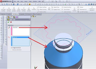
The Cut-Extrude feature was made before
the Shell feature was added.
In the Feature Manager design tree, the
Shell feature icon was dragged and
dropped before Cut-Extrude icon.


SolidWorks 2004
Reference Guide

Comments Off

Workflow customization

To customize the user interface by work flow: Click Tools, Customize, or right-click in the window border and select Customize. On the Options tab, under Work flow customization, select one or more of: Consumer product design Machine design Mold design Click OK. Special menu and toolbar settings are made for Consumer product design, Machine design, or Mold design. After the software is initially installed, you only see this screen once, but you can change all the options in other places, including the Options tab in the Customize dialog box. The three-workflow customizations affect the interface as follows: Consumer product design adds the Surfaces toolbar to the CommandManager. Machine design adds Sheet Metal and Weldments toolbars to the CommandManager. Mold design adds Surfaces and Mold Tools toolbars to the CommandManager. Similar changes are made to the menus to hide or show menu selections as appropriate. You can find more information about hiding and showing menu items later in this chapter. If you want to select a different option after the initial setup, choose Tools ➪ Customize and click the Options tab, where you can specify a different choice. Figure 2.20 shows the Options tab of the Customize dialog box.

  • Read more........
  • Comments Off

    Split Line tool

    Split Line tools to project entities such as sketches, solid, surface, face, plane, or surface spline to surfaces, or curved or planar. It divides the selected face into several separate face. we can divide the curve on some solid body with a single command. We can make a line following divisions: Projection. Projection sketch on the surface. We can divide the pattern line features created using projection curves. We can make use of text split line sketch. This is useful for making items such as decals. Silhouette. Make the split line on the cylinder. Intersection. Splits face with intersecting solid, surface, face, plane, or spline surface. When we make a line break with an open profile sketch, sketch must span at least tw o sides of the model


    Creating Lines Split When we made the split lines, edges do not change that can be reused in the downstream and changed the update feature edges.  In this model we insert line splits at the front face as the last item in the FeatureManager design tree. If we change the order Line1 Split follow Extrude1 features, models defend downstream chamfer and fillet. 


    To create a projection split line:Click Split Line (Curves toolbar) or Insert, Curve, Split Line. In the PropertyManager, under Type Split, select Projection. Under Selection, click: A sketch for Sketch for the Project. We can choose some of the contours of the same sketches to share. face-face to project sketches for face to Split. One way to project the split line in only one direction.Click OK. To create a split line silhouette:Click Split Line (Curves toolbar) or Insert, Curve, Split Line. In the PropertyManager, under Type Split, click Silhouette. In Selection: Select the plane to the project through the silhouette of the model (the outside) for Direction of Pull. Select the face to face project for the plane to Split. face can not be planar. Set Angle to create a draft angle.Click OK. To create a line of cleavage junction:Click Split Line (Curves toolbar) or Insert, Curve, Split Line. In the PropertyManager, under Type Split, select Intersection. In Selection: Choose a splitting tool (solid cut, surface, face, plane, or surface splines) for Non Separates / face / Planes.Click on the face / body to Split, and select the target face or body that projected splitting tool.Click OK


    Comments Off

    Solidworks Boss-Extrude, circular pattern

    Step 1. Create a circle with a diameter of 85 sketches, on the top plane


    Step 2. Boss-Extrude1, to create a pedestal table.
    Click Insert> Boss> Extrude
    From the property manager, Direction 1
    select offset, input the number 75
    select the Blind, with a thickness of 5


    Step 3. Create a circle with a diameter of 15 sketches, the top plane.


    Step 4. Boss-Extrude2, to make the pole table.
    Click Insert> Boss> Extrude
    From the property manager, Direction 1
    select the Up to Surface
    select the face that will be made in reference


    Last step. circular pattern, to create a table leg.
    Click Insert> patern / mirror> circular pattern


    Comments Off
    Powered by Blogger.